
Membrane Technology
MBR Membrane Sludging and Clogging: Causes, Diagnosis, Prevention and Recovery
Understand how MBR membrane sludging and clogging differ from ordinary fouling, how to diagnose causes, and how screening, aeration, and cleaning reduce risk.
What is MBR membrane sludging or clogging?
MBR operators often use “sludging,” “clogging,” “matting,” or “ragging” to describe solids-related blockage around or inside membrane modules. The terms should not be treated as exact synonyms in every plant. In this article, sludging or clogging means a localized accumulation or agglomeration of solids that restricts liquid and air movement through membrane channels, between membrane surfaces, around module supports, or at channel and aerator entrances.
This differs from ordinary membrane fouling. Fouling generally refers to material deposited on the membrane surface, material entering or narrowing membrane pores, or a cake layer that increases filtration resistance. Sludging is more strongly associated with the physical accumulation, dewatering, bridging, and agglomeration of suspended solids in a location where they obstruct circulation or cannot be removed by normal filtration-side cleaning. The two phenomena can occur together and may produce the same plant-level symptoms: declining permeability, increasing TMP, reduced capacity, or increased cleaning frequency [1] [2].
The distinction matters because a chemical clean may remove organic or inorganic deposits on a membrane surface but may not remove a physically lodged mass of fibrous solids, hair, rags, grit, or dewatered sludge inside a channel. A plant can therefore continue to show poor performance after a chemically successful cleaning if the underlying problem is a blocked channel, obstructed aerator, or damaged module pathway.
Sludging, ragging and matting: related but different conditions
| Term | Typical meaning | Where it may appear | Why it matters |
|---|---|---|---|
| Sludging or localized dewatering | Solids concentrate and dewater within membrane channels or around a module, forming a dense deposit | Flat-sheet gaps, hollow-fibre bundles, cassette edges, or low-circulation areas | Restricts mixed-liquor movement, air distribution, and effective membrane area |
| Clogging | A broader term for blockage of a channel, aerator, passage, or module region | Membrane channels, air-scour diffusers, recirculation paths, and screen systems | Can cause localized loss of filtration capacity and uneven loading across a train |
| Ragging or braiding | Fibrous material entangles into ropes, bundles, or rag masses | Around racks, module frames, pumps, pipework, aerators, and channel entrances | Can obstruct air and liquid paths and may mechanically damage module components |
| Matting | A dense mat or carpet of accumulated material blocks channel entrances or module surfaces | Frequently observed at the entrance to flat-sheet channels or around fibre bundles | Prevents effective air scouring and can make normal cleaning ineffective |
| Surface fouling | Soluble, colloidal, microbial, organic, or inorganic material forms a deposit on the membrane surface | Membrane skin or pore entrances | Often responds more readily to approved physical or chemical cleaning than lodged solids do |
The categories are operational aids, not laboratory diagnoses. A single incident may involve fine cake deposition, fibrous ragging, channel matting, and pore fouling at the same time.
Why sludging can occur in an MBR
Sludging is usually a system interaction rather than a single-parameter failure. Potential contributors include solids entering the membrane tank, a wastewater stream with fibrous or stringy material, inadequate fine screening, high or poorly controlled mixed-liquor solids, weak air-scour distribution, excessive solids residence in a channel, high applied flux, poor sludge dewaterability, and module geometry that creates low-velocity or poorly swept regions [1] [2].
Coarse solids, fibres and rag formation
Hair, wipes, textiles, plastic fragments, grease-bound fibres, food residues, and other coarse suspended solids can pass through inadequate screening or enter the process during a bypass, maintenance event, screen failure, or abnormal hydraulic condition. These materials may entangle around racks and supports or combine into larger masses after entering the bioreactor. A screen that protects the membrane surface from individual particles does not necessarily prevent downstream reformation of fibrous rags.
The required screen arrangement is configuration- and supplier-specific. A general municipal screen rating should not be copied into an MBR design without considering the membrane passage, aerator geometry, pump arrangement, upstream equalization, and the supplier’s capture and bypass requirements. The practical question is not only “What is the screen opening?” but also “What happens to captured and reformed solids after the screen?”
Inadequate or uneven air scouring
Air scouring helps create liquid movement, bubble-induced shear, and solids displacement near submerged membranes. If the air flow is too low, poorly distributed, intermittently unavailable, or obstructed by solids, deposits may accumulate in areas that receive insufficient sweep. A blocked or damaged diffuser can create a local cycle in which solids collect, the air path becomes weaker, and the resulting blockage grows further.
Increasing blower flow is not automatically a safe solution. Excessive air can waste energy, damage delicate components, disturb floc structure, increase foaming, or fail to correct a localized distribution problem. Operators should inspect the diffuser and manifold condition, compare train-to-train air distribution, confirm valve and instrument operation, and follow the membrane supplier’s validated air-scour envelope [3].
Mixed-liquor concentration and sludge rheology
High MLSS, elevated viscosity, poor dewaterability, filamentous growth, abnormal floc structure, or a high fraction of inert and fibrous solids can reduce circulation through membrane channels and make deposits more cohesive. The same nominal MLSS concentration can behave differently at different temperatures, SRTs, organic loading conditions, sludge ages, and wastewater compositions.
MLSS and MLVSS trends should therefore be interpreted with sludge settleability, viscosity or rheology indicators where available, microscopy, particle-size observations, filterability tests, and wasting history. A sudden increase in solids concentration or a long period without effective wasting may be relevant, but a blind reduction of MLSS can undermine nitrification, oxygen transfer, or effluent objectives. Corrective action should follow a process diagnosis rather than a single target number.
Flux, residence time and localized dewatering
Higher flux can increase the rate at which water is withdrawn from the mixed liquor adjacent to a membrane surface. If solids remain in a channel for too long, local dewatering and agglomeration may become more likely. Module geometry, air movement, liquid circulation, train loading, and permeability distribution can create local conditions that are not represented by the average plant flux.
For that reason, a plant can meet an average design flux while still experiencing a localized blockage in one cassette, one corner of a tank, one air-scour zone, or one fibre bundle. Uneven permeate distribution and train-to-train differences are useful diagnostic clues.
Which membrane arrangements are vulnerable?
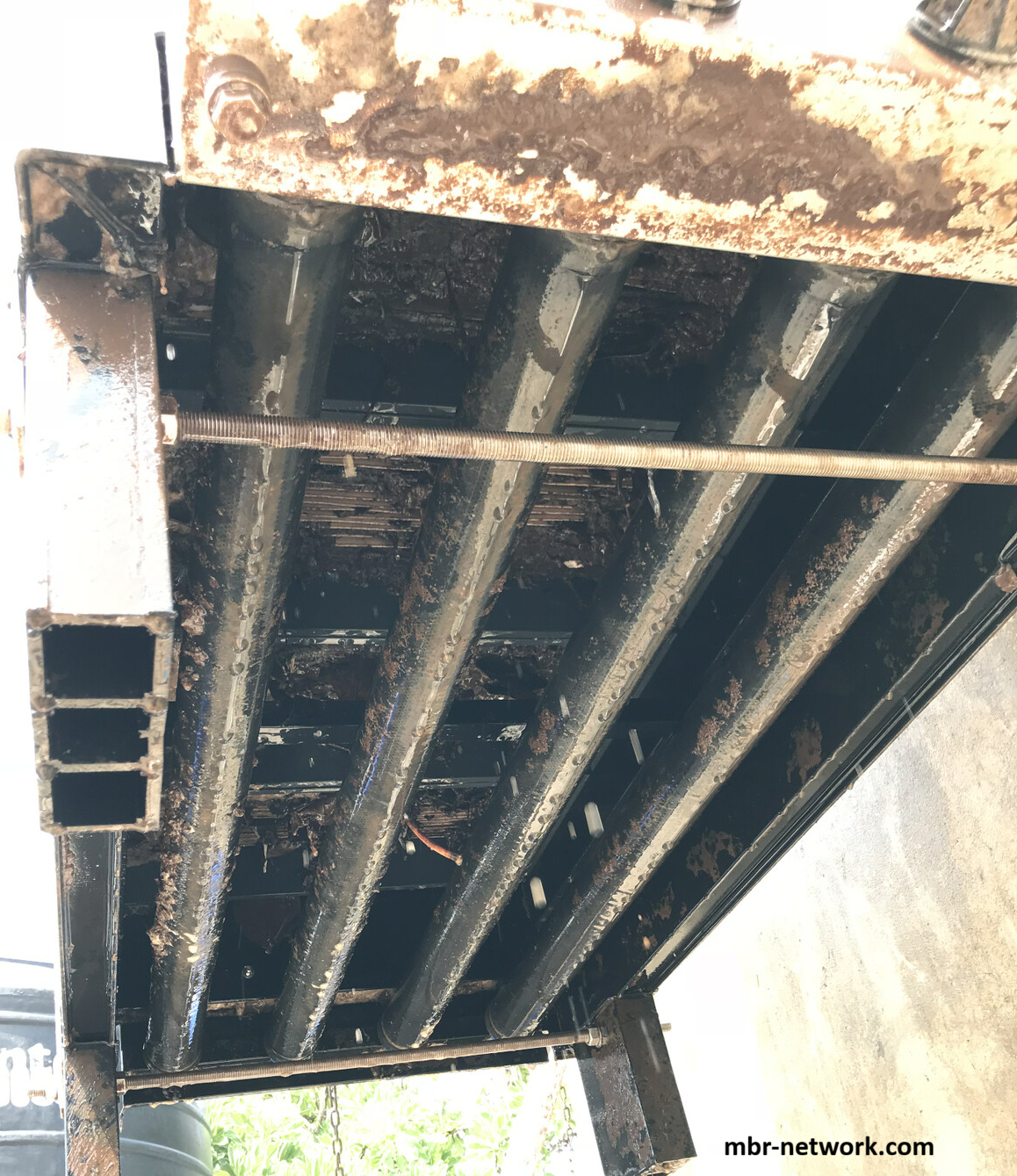
Field photograph: clogging and accumulated solids between membrane sheets. The condition illustrates why channel spacing, air distribution, screening, and early inspection matter; it is not a substitute for an OEM inspection procedure.
Sludging can affect both flat-sheet and hollow-fibre systems, although the visual pattern and recovery procedure may differ. Flat-sheet systems can experience blockage between plates, at plate-channel entrances, around cassette frames, and near air-distribution components. Hollow-fibre systems can experience solids accumulation within or around fibre bundles, at bundle headers, and in regions where fibre movement or bubble transport is restricted. Tubular or sidestream systems have larger hydraulic passages but can still experience solids deposition, ragging, pump-side blockage, or loss of cross-flow effectiveness.
| Configuration | Typical sludging or clogging concern | Diagnostic emphasis |
|---|---|---|
| Flat sheet or flat plate | Channel-entrance matting, deposits between plates, cassette obstruction, uneven air distribution, and structural or sealing stress | Inspect channel access, cassette spacing, air distribution, plate integrity, and whether a physical deposit remains after approved cleaning |
| Hollow fibre | Bundle matting, fibre entanglement, solids accumulation around headers, impaired bubble passage, and permeability loss | Compare bundle appearance, air-scour pattern, train performance, fibre integrity, and the condition of screens and recirculation paths |
| Tubular or multichannel sidestream | Passage deposition, ragging, pump or recirculation obstruction, and reduced cross-flow velocity | Check feed screening, pump strainers, differential pressure, recirculation flow, passage inspection, and cleaning response |
The guide should be used together with the site’s membrane configuration page and the OEM module manual. A configuration label alone cannot predict the risk because the channel width, fibre spacing, air-distribution system, permeate connection, module packing, and process controls vary by product.
How to recognize a possible sludging event
Sludging should be considered when filtration performance changes in a way that does not match a normal, distributed fouling trend. Important observations include a sudden or localized permeability loss, rising TMP in one train or cassette group, unequal permeate flow, unexpected differences in air pressure or air flow, persistent loss of performance after an approved chemical clean, visible solids mats, abnormal rag accumulation, repeated diffuser blockage, and evidence of solids at module or channel entrances.
| Observation | Possible interpretation | Checks before intervention |
|---|---|---|
| Whole plant permeability declines gradually | Distributed fouling, biological change, temperature effect, or operating-envelope drift | Confirm temperature correction, flux, TMP, permeability calculation, MLSS/MLVSS, air flow, and cleaning history |
| One train declines faster than the others | Local module, air-scour, instrument, valve, or solids-distribution problem | Compare train air flow, permeate flow, TMP, valve state, diffuser pressure, and recent maintenance |
| Performance does not recover after chemical cleaning | Physical blockage, damaged component, incorrect chemistry, poor contact, or measurement error | Verify cleaning execution and compatibility, inspect the module or channel, and compare direct evidence with trend data |
| Air pressure rises or air flow falls in one zone | Diffuser or manifold obstruction, valve fault, condensate, or instrument problem | Check isolation, valve response, pressure measurement, diffuser condition, and safe access requirements |
| Rags or fibrous mats are visible | Screening, ragging, housekeeping, recirculation, or solids-routing problem | Record location and material, review screen operation and bypass history, inspect affected equipment safely |
| One cassette shows poor flow with normal average tank values | Local channel obstruction, uneven air scour, sealing issue, or module damage | Compare cassette-level data and perform OEM-approved inspection rather than changing plant-wide setpoints immediately |
A trend review should compare flux, TMP, permeability, temperature, MLSS, wasting, air flow, air pressure, permeate quality, cleaning events, screen alarms, pump status, and maintenance records. The question is whether the evidence points to a distributed membrane-surface resistance or a physical obstruction in a specific flow path.
A practical diagnostic sequence
1. Stabilize and confirm the signal
Confirm that the reported decline is real. Check instruments, calibration status, temperature compensation, flow-meter behaviour, permeate sampling, valve positions, and train isolation. Avoid changing several operating variables at once because that can obscure the cause and make the recovery sequence difficult to interpret.
2. Check for air-scour and hydraulic asymmetry
Compare air flow, pressure, valve status, blower loading, diffuser condition, and bubble distribution between affected and unaffected trains. Inspect whether air is reaching the intended membrane zone. Review recirculation flow and pump strainers where applicable. A localized air or liquid-distribution problem can resemble a membrane-fouling event.
3. Review solids entry and solids condition
Check fine-screen operation, bypass history, screen differential pressure, captured solids, ragging, grease, unusual industrial discharges, storm or infiltration events, and maintenance records. Review MLSS/MLVSS, SRT, wasting, settleability, viscosity or filterability indicators, microscopy where available, and the presence of filamentous or fibrous material.
4. Compare the cleaning response
If an approved physical or chemical cleaning was performed, compare the pre- and post-clean permeability, TMP, flow, contact conditions, chemical compatibility, and train response. Failure to recover does not prove clogging, but it is a reason to investigate physical blockage, ineffective contact, instrument error, or module damage rather than repeatedly increasing chemical strength.
5. Inspect under an approved isolation and safety procedure
A physical inspection may be necessary when the evidence indicates a blocked channel, matted cassette, ragged bundle, blocked aerator, or solids lodged in a support structure. The inspection must follow lockout/tagout, confined-space, biological exposure, lifting, chemical, and OEM requirements. Photograph and document the condition before cleaning where practical.
Prevention and operating controls
Protect the membrane system with a complete solids-management chain
Screening is important, but screening alone is not the whole control strategy. The plant should consider coarse and fine screening, screen capture performance, bypass protection, screen cleaning, rag disposal, equalization, grease control, recirculated mixed-liquor routing, aerator protection, and access for inspection. A screen can capture incoming debris while fibrous material reforms downstream, so the membrane tank and recirculation paths must also be managed.
Maintain effective air distribution, not simply high air flow
The objective is adequate and uniform membrane-zone movement within the supplier’s operating envelope. Operators should track blower and zone pressure, valve position, air flow where measured, diffuser fouling, and train-to-train differences. If air-scour performance is abnormal, inspect distribution hardware before applying a blanket blower increase.
Keep solids conditions within the validated process envelope
Control wasting, SRT, MLSS, MLVSS/MLSS, return and recycle patterns, oxygen transfer, nutrient balance, and sludge age in a way that supports both biology and membrane operation. Investigate changes in floc structure, viscosity, dewaterability, filamentous growth, and inert solids rather than assuming that one MLSS number defines risk.
Use configuration-specific inspection and maintenance
For flat-sheet systems, inspect cassette spacing, channel entrances, plate or flexible-sheet condition, air distribution, permeate connections, seals, and frame integrity. For hollow fibre systems, inspect bundle condition, headers, fibre movement, air distribution, and integrity-test results. For tubular or sidestream systems, inspect recirculation pumps, strainers, passage differential pressure, and cross-flow performance.
Mitigation and Recovery Cleaning
Mitigation and recovery should be managed as a staged response rather than as an automatic increase in blower air or chemical strength. The first objective is to prevent further accumulation while confirming whether the event is distributed membrane fouling, localized channel blockage, ragging, aerator obstruction, or module damage. The second objective is to recover the affected filtration area using an approved method that does not exceed the membrane, module, seal, permeate-connection, or support-structure limits.
Immediate mitigation while the cause is being confirmed
If safe operating conditions permit, stabilize or reduce the applied flux on the affected train, compare it with unaffected trains, and maintain the process within the supplier’s validated operating envelope. Confirm that air-scour blowers, valves, diffusers, recirculation pumps, screens, and instruments are functioning. Remove the affected train from service only through the approved plant procedure; do not create uncontrolled hydraulic or biological upset by abruptly changing all trains at once.
Record the time of onset, affected train or cassette, permeability and TMP trend, air flow and pressure, screen alarms, bypass history, MLSS and sludge condition, and any visible rag or solids accumulation. If coarse debris or fibrous material is still entering the system, correct that pathway before attempting repeated membrane cleaning. Otherwise, the same material may rapidly re-form after recovery.
Physical recovery for lodged solids, ragging, or channel matting
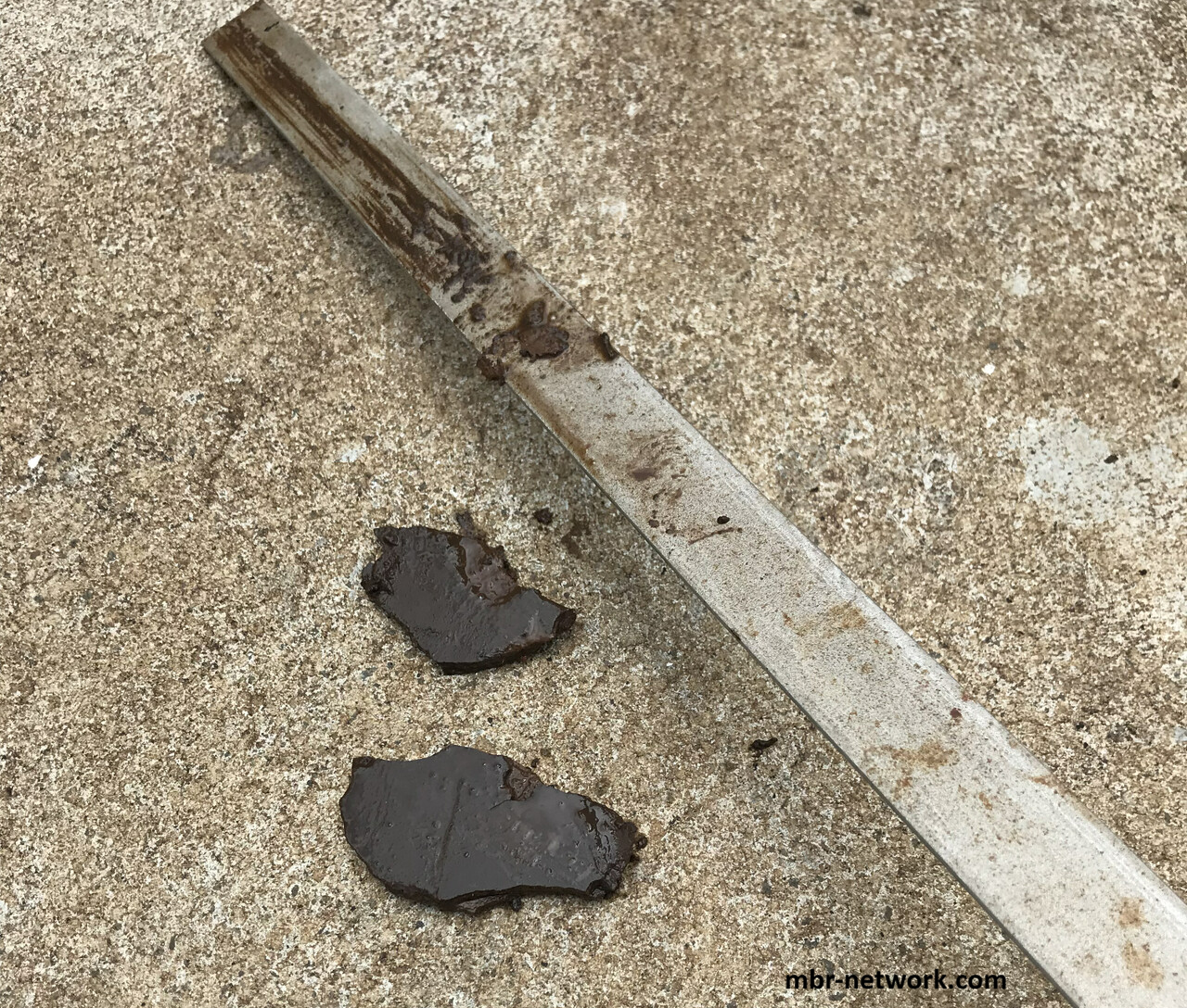
Field photograph: dried, cohesive sludge removed from between membrane sheets. Hardened deposits can require controlled physical recovery after ordinary aeration and chemical soaking no longer provide sufficient access or movement.
Chemical cleaning is often insufficient when solids are physically lodged between flat-sheet plates, around a cassette, within a hollow-fibre bundle, at a channel entrance, or across an aerator. In that situation, recovery may require controlled isolation, draining or lowering the relevant tank level, module lifting, cassette or bundle inspection, and OEM-approved physical cleaning outside the operating tank. The exact method may involve controlled flushing, brushing, low-pressure washing, or another supplier-approved technique, but the pressure, nozzle, water quality, lifting arrangement, access method, and worker protection must be specified by the responsible engineer and membrane supplier.
Do not use a high-pressure jet, sharp tool, improvised scraper, or manual entry simply because a channel appears blocked. These actions can cut fibres, delaminate a membrane layer, deform a plate, damage a diffuser, open a seal, or create a defect that is not immediately visible. For submerged systems, the work plan must address lockout/tagout, biological exposure, confined-space risks, lifting, electrical equipment, chemical residues, and safe disposal of removed sludge and screenings.
Approved physical cleaning and pressurized methods
Where the selected membrane system is designed for relaxation, backwash, backflush, air pulsing, or another pressure-assisted cleaning method, use only the OEM-approved sequence and pressure/flow envelope. Pressurized cleaning can be useful for reversible deposits and some membrane designs, but it does not guarantee removal of a mechanically lodged sludge mass. The responsible engineer should verify pump capacity, valve sequencing, pressure measurement, discharge routing, permeate-channel integrity, and the risk of forcing solids deeper into a module.
For backwashable flat-sheet products, a successful pressure-assisted clean should be demonstrated by documented permeability recovery and stable post-clean performance rather than assumed from the fact that reverse flow was applied. If the pressure limit, seal condition, or module integrity is uncertain, stop the pressurized sequence and escalate to the supplier.
Chemical cleaning: when it helps and when it does not
Chemical cleaning can remove or loosen membrane-surface deposits such as organic material, biofilm, or inorganic scale when the chemical, concentration, temperature, contact time, flow direction, and compatibility limits are approved for the installed membrane. It is not a universal response to sludging. A chemically clean membrane surface may still be surrounded by a compacted solids mass, a blocked channel entrance, a clogged aerator, or a ragged cassette.
Do not increase chemical concentration or contact time to compensate for a physical blockage without written approval. Chemical selection must consider the membrane polymer or ceramic, support layers, potting, adhesives, seals, permeate tubing, stainless steel, elastomers, wastewater residues, discharge limits, and worker exposure. Follow the approved site procedure and OEM compatibility matrix rather than a generic recipe.
Inspection, return to service, and verification
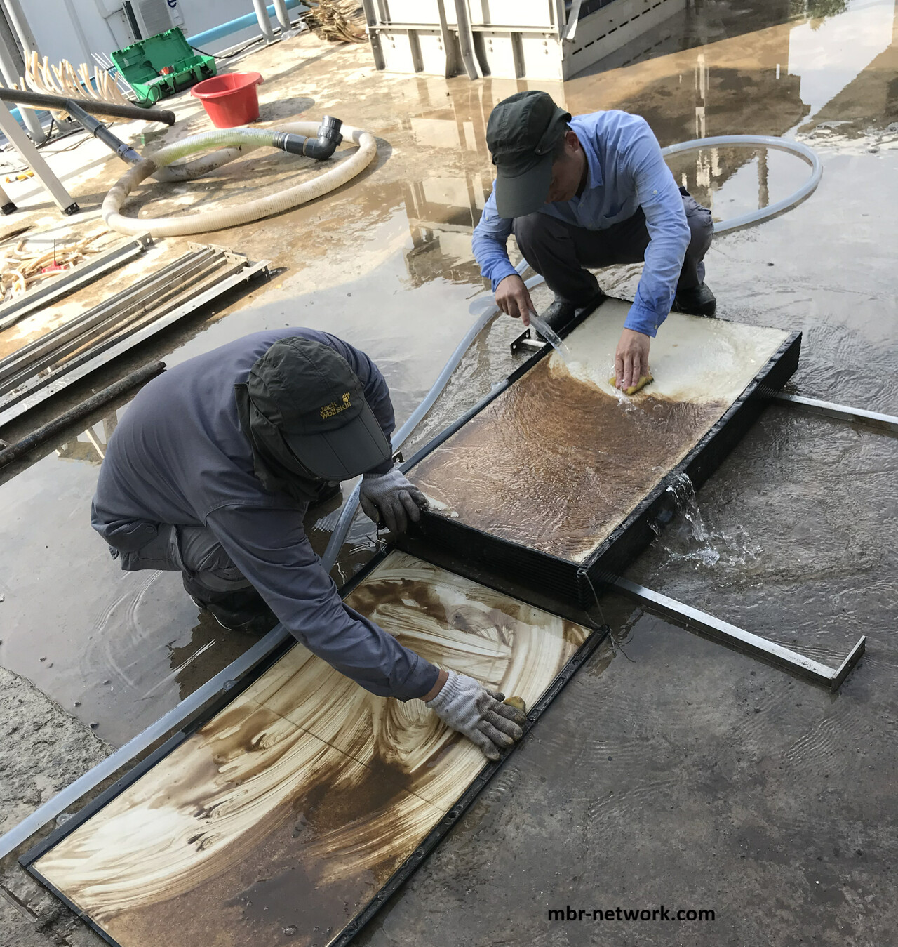
Field photograph: manual scrubbing of removed membrane plates. This is an intensive maintenance activity that requires isolation, safe access, suitable PPE, controlled wastewater handling, and confirmation that the membrane supplier permits the method.
After physical or chemical recovery, inspect the membrane element, channel entrances, aerators, frame or cassette, permeate connections, seals, headers, lifting points, and surrounding tank equipment. Recommission gradually under the approved procedure. Confirm that air distribution, permeate flow, TMP, permeability, temperature correction, and effluent quality return to a stable condition, and compare the recovered train with an unaffected train.
A recovery should not be declared successful solely because the first post-clean flow increases. Continue trending for recurrence, uneven air distribution, renewed solids accumulation, leakage, integrity-test anomalies, or faster permeability decline. Where the membrane is an integrity barrier, complete the applicable OEM integrity test before returning the train to normal service.
Recurrence prevention after recovery
Close the event by identifying the pathway that allowed the solids to accumulate. Corrective actions may include screening or bypass improvements, rag-management changes, diffuser or air-manifold repair, recirculation-path protection, revised inspection frequency, controlled wasting or sludge-condition adjustments, module-spacing or access changes, and updated alarm response. Record the event location, observed material, screen and bypass status, MLSS and sludge condition, air-scour performance, cleaning actions, module condition, photographs, post-recovery test results, and preventive changes. This record supports warranty discussions and distinguishes a one-time solids event from a recurring design or operating weakness.
Editor’s engineering perspective: prevent the disaster stage
In the editor’s field experience, the appearance of serious sludging in an MBR is often a sign that monitoring, inspection, alarm response, or routine cleaning has not detected the developing problem early enough. By the time sludge has accumulated into a dense mass, routine chemical soaking and membrane-zone aeration may have little or no practical effect because the obstruction is no longer simply a surface deposit. It may be physically lodged between flat-sheet membranes, around a cassette, or within a fibre bundle.
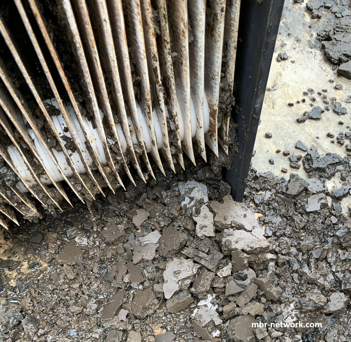
Field photograph: heavy sludging on a membrane module. The condition illustrates the late-stage accumulation that early monitoring and inspection should prevent.
At advanced stages, the sludge can harden into a compact, cohesive mass with a texture that operators may compare to a hardened cake or chocolate bar. Recovery may then require controlled physical cleaning. Carefully controlled spraying or jetting can be used in some systems, but the pressure, nozzle, distance, water quality, access method, and membrane orientation must be specified or approved by the membrane supplier and responsible engineer. Excessive jet pressure can cut fibres, damage membrane skins, open seals, deform support plates, or void membrane and module warranties.
If less aggressive methods are ineffective, a last-resort recovery may involve manual dislodging using gloved hands or approved tools under a controlled maintenance procedure. Where individual membrane plates can be safely removed from the tank, intensive manual scrubbing with suitable cloths or sponges may be possible for some flat-sheet designs. These are not routine operating methods: they require isolation, draining or level control, lifting and access planning, biological-exposure controls, chemical-safety review, and documented OEM acceptance. Flat bars, scrapers, or other tools should never be used as improvised equipment against an unapproved membrane surface or support structure.
The practical lesson is preventive. Regular visual inspection, earlier review of permeability and TMP trends, air-scour checks, screening checks, and prompt removal of small accumulations are substantially preferable to waiting until a cassette, fibre bundle, or aerator reaches a disaster-stage blockage. Early intervention may preserve the module, reduce downtime, avoid intensive manual work, and prevent a localized solids problem from becoming a plant-wide capacity and reliability event.
Sludging prevention checklist
| Control area | Questions for the operator or designer |
|---|---|
| Influent protection | Are coarse and fine screens sized for the selected membrane and protected from bypass? Are captured fibres and rags removed reliably? |
| Solids routing | Can rags reform downstream of screening? Are recirculation lines, strainers, pumps, and membrane-tank entries protected? |
| Membrane aeration | Is air distributed across the complete module footprint? Are diffuser blockage and zone imbalance detected? |
| Sludge condition | Are MLSS, MLVSS/MLSS, SRT, viscosity or filterability, filamentous growth, and inert solids reviewed together? |
| Module design | Are channel openings, cassette spacing, fibre headers, supports, seals, and cleaning access suitable for the wastewater? |
| Monitoring | Are permeability, TMP, flux, air flow/pressure, train comparison, screen alarms, and cleaning response trended? |
| Recovery readiness | Are isolation, lifting, inspection, physical-cleaning, chemical-safety, and OEM escalation procedures available? |
Recommended internal links
This article should link to the Fouling Mechanisms, Monitoring & Prevention guide, Membrane Air Scouring guide, Membrane Cleaning guide, Membrane Types & Materials guide, Flat-Sheet MBR Membranes guide, MBR Monitoring & Troubleshooting guide, and the Membrane Air-Scour Demand Calculator.
Limitations
This page is an engineering education reference, not a universal cleaning procedure or operating setpoint. Screen openings, air-scour rates, MLSS limits, flux targets, backwash pressures, jet-cleaning methods, chemical concentrations, contact times, and module-removal procedures must be taken from the selected membrane supplier, approved design basis, site risk assessments, and applicable permits. If the supplier’s instructions conflict with a generalized recommendation, the supplier’s approved procedure and the responsible engineer’s site-specific decision govern.
By: mbr-network.com
Proposed last reviewed: September 12, 2026
Related guides
Continue with the Fouling Mechanisms, Monitoring & Prevention guide, MBR Membrane Air Scouring, Membrane Cleaning, and MBR Monitoring & Troubleshooting.