
Membrane Technology
MBR Membrane Air Scouring: Types, Design & Selection
Understand why air scouring is central to submerged MBR operation, how scouring designs have evolved, and how to select a membrane-and-aeration package for performance, maintainability, CAPEX, and whole-life OPEX.
Scope and limitation. This guide explains the engineering purpose and selection logic for air scouring in submerged membrane bioreactors. It does not provide a universal air-flow setpoint, blower size, membrane warranty condition, or guaranteed energy performance. Final values must be established from the selected membrane supplier’s validated design data, pilot or reference-plant evidence, process design basis, approved operating procedures, and site-specific testing.
Why air scouring matters in an MBR
In a submerged membrane bioreactor, permeate is withdrawn through membrane surfaces while mixed liquor remains on the biological-treatment side. The membrane surface therefore experiences a continuous tendency for solids, colloids, extracellular polymeric substances, and other foulant material to accumulate. As the deposited layer becomes more resistant to flow, transmembrane pressure can rise at constant flux, or permeate production can fall at constant pressure.
Membrane air scouring introduces gas below or within the membrane module so that rising bubbles generate local shear, liquid movement, turbulence, and solids displacement. The objective is not simply to “wash” the membrane with air. It is to manage the balance between deposition and removal while maintaining the required permeability with the lowest practical air demand. The MBR Site describes membrane aeration as a distinct duty from process aeration: coarse-bubble aerators are generally used for membrane scouring, while fine-bubble diffusers are normally used to transfer oxygen in the biological process [1].
Air scouring is important for four related reasons:
- It helps control the reversible cake layer and reduces the rate at which membrane resistance increases.
- It promotes mixed-liquor movement through or around the module, reducing stagnant regions and uneven solids accumulation.
- It protects membrane availability and operating stability, particularly when the plant is operating near its sustainable flux or under high-solids conditions.
- It can be one of the largest energy demands in an MBR, so excessive air is an operating-cost problem rather than a harmless safety margin [1] [2].
A successful design therefore seeks sufficient and well-distributed shear, not the highest possible air rate. Excessive air can increase blower power, noise, vibration, aerosol generation, evaporation, foaming, and floc break-up, while also producing little additional fouling-control benefit.
Membrane-scouring air is not the same as biological aeration
The same tank may contain two aeration duties with different objectives. Biological process aeration supplies oxygen for carbon oxidation and nitrification and maintains the required dissolved-oxygen condition. Membrane-scouring aeration creates hydrodynamic action at the membrane surface and within the module. The two duties may interact hydraulically, but they should remain distinct in the design calculation and operating record.
Fine-bubble diffusers are often selected for oxygen-transfer efficiency in the aerobic bioreactor. Membrane modules more commonly use coarse-bubble or large-bubble arrangements beneath the membrane zone because larger bubbles and slugs create stronger bulk liquid movement and membrane-surface shear. A module supplier may combine membrane aeration with an airlift tube, internal circulation passage, pulsing device, or specialized diffuser geometry. These arrangements must be evaluated from the supplier’s module-level performance data rather than inferred from the oxygen-transfer diffuser specification.
A useful design record should therefore identify at least four separate quantities:
| Quantity | Meaning | Why it should be recorded separately |
|---|---|---|
| Biological process-air flow | Air delivered for oxygen transfer and biological mixing | Used for oxygen-transfer, DO-control, and biological capacity checks |
| Membrane-scouring air flow | Air delivered to the membrane module or membrane zone | Used for fouling control, module hydrodynamics, and membrane energy analysis |
| Specific aeration demand by membrane area, SADm | Air flow normalized by installed or online membrane area | Useful for comparing modules with different membrane areas |
| Specific aeration demand by permeate, SADp | Air flow normalized by permeate production | Useful for assessing air energy per unit of treated water |
The normalisation basis must be stated clearly. “Air per square metre” and “air per cubic metre of permeate” answer different questions and can produce very different-looking values when flux or membrane availability changes.
How air scouring controls fouling
Bubble-induced shear and liquid circulation
As a bubble rises, it transfers momentum to the surrounding mixed liquor. A train of bubbles can generate an upward liquid velocity along membrane fibres or plates. This movement reduces the thickness and stability of the deposited layer and helps prevent local solids concentration from remaining high at the membrane surface.
Intermittent disturbance of the cake layer
Continuous air is not the only possible strategy. Intermittent or pulsed air can create a repeated disturbance that disrupts deposited solids while allowing the average air rate to fall. The appropriate pulse duration, frequency, and recovery time depend on module geometry, solids condition, flux, viscosity, and the supplier’s validated operating envelope.
Reduction of channeling and dead zones
A poorly distributed air system may create a few high-velocity paths while leaving other parts of the module under-scoured. Module geometry, membrane packing density, diffuser position, header balance, liquid depth, and obstruction by rags or settled solids all affect the distribution. A higher total air rate cannot reliably compensate for a fundamentally uneven distribution.
Interaction with mixed-liquor properties
The same air flow can have a different effect when MLSS, viscosity, temperature, floc structure, or gas hold-up changes. Recent full-scale research has described the required scour flow as a balance between particle deposition, driven partly by permeate flux and fouling condition, and removal caused by air-induced shear. The research identifies air flow, permeate flow, MLSS, viscosity, membrane packing density, and total resistance as important variables [2].
From side-stream cross-flow to immersed membrane air scouring
The development of immersed or submerged MBRs is closely linked to the search for a more practical way to control membrane fouling than circulating the entire mixed liquor through external membrane channels at high cross-flow velocity. Early side-stream MBRs placed the membrane outside the bioreactor and used pumps to drive mixed liquor through tubular or channel-type membrane modules. This configuration predates the now more widespread immersed arrangement and was already being developed in the late 1960s and early 1970s, while immersed systems were commercialized later [5].
In a side-stream system, cross-flow velocity is a primary hydrodynamic tool. The recirculation pump must maintain enough velocity along the membrane surface to limit deposition, which can deliver higher membrane flux in some applications but also creates a substantial pumping and heat-load requirement. This configuration remains valuable where high flux, external access, abrasive or high-solids service, or specialized industrial operation justify the additional recirculation equipment.
Immersed MBRs changed the balance. Instead of pumping the full mixed-liquor circulation loop through external modules, membrane elements were placed in the bioreactor or a connected membrane tank and permeate was withdrawn under relatively low pressure. Air introduced below or within the membrane modules created rising bubbles, local shear, and airlift-driven liquid circulation. The useful cross-flow was therefore generated locally by the interaction of bubble flow, module geometry, and mixed liquor rather than relying only on a large external recirculation pump [1] [5].
This pairing of membrane modules with membrane-scouring aeration helped make immersed MBRs viable at the scale and operating cost required for municipal and many industrial applications. The advantage was not caused by air scouring alone. It emerged from the combined development of lower-pressure membrane operation, hollow-fibre and flat-sheet module engineering, coarse-bubble aeration, improved air distribution, pretreatment, permeability monitoring, relaxation and backwash sequences, and more reliable control systems. A peer-reviewed review describes the broad configuration trade-off as lower flux and lower power for submerged MBRs versus higher flux and higher power for side-stream MBRs, while also noting that performance depends on the complete design and operating context [6].
The historical lesson is therefore not that immersed MBRs eliminated cross-flow. They changed how cross-flow-like liquid movement and membrane-surface shear were produced. The best modern designs still depend on module-specific hydrodynamics and adequate circulation; they simply obtain much of that action from controlled aeration and internal module flow rather than from continuously pumping the complete mixed-liquor stream through an external membrane loop.
Main types of MBR membrane air scouring
1. Continuous coarse-bubble scouring
Continuous coarse-bubble scouring supplies air throughout membrane filtration. The diffuser or aeration grid is normally placed below the membrane modules so that bubbles rise through the module zone and maintain bulk circulation.
This is a robust and familiar arrangement, particularly where simple controls and predictable hydraulic behaviour are valued. It can be easier to commission than a complex pulsed system, but it may consume more energy during low-load or low-flux periods. Continuous operation also makes it important to verify that the air distribution remains balanced rather than assuming that the blower flow is reaching every module equally.
Typical applications: municipal plants with stable continuous loading, modules with established coarse-bubble guidance, and installations where the operational simplicity is worth more than the potential energy saving from advanced control.
2. Intermittent or cyclic air scouring
Intermittent scouring alternates between higher-air and lower-air or no-air periods while filtration, relaxation, backwash, or backpulse continues according to the membrane system’s operating sequence. The aim is to maintain fouling control using the average air demand more efficiently than a fixed continuous rate.
The risk is that an overly aggressive reduction may allow the membrane surface to cross into a rapid-fouling regime before the next high-air period. Intermittent operation must therefore be supported by trend monitoring, train-level permeability data, validated recovery behaviour, and defined return-to-normal logic.
Control-complexity note: Cyclic aeration needs valves or equivalent switching hardware to control the air-flow pattern. It can save scouring energy when properly validated, but it adds control complexity, sequencing requirements, instrumentation, and failure modes compared with a simpler continuously supplied arrangement.
3. Pulsed or slug air scouring
Pulsed systems introduce larger air volumes at controlled intervals. The resulting bubbles or slugs can create a stronger temporary disturbance than a steady small-bubble flow. Some module designs use a random or controlled slugging effect and an airlift path to draw mixed liquor through the module. DuPont describes this type of module-integrated concept for its MemPulse system, including large bubbles or slugs, airlift circulation, and cross-flow through the membrane fibres [3].
Pulsed aeration has become a mainstream design approach in many contemporary immersed MBR products. It can be more efficient because proprietary or patented module and air-distribution designs create useful bubble or slug action without requiring the same cyclic valve-control arrangement used by intermittent aeration. The exact hardware remains supplier-specific: some designs generate the pulse through module geometry, airlift paths, air chambers, or other internal features, while others may still use valves or controlled sequencing. The supplier should provide evidence that the pulse pattern is compatible with the module structure, membrane-fibre movement limits, and the intended operating envelope.
4. Module-integrated airlift or cross-flow arrangements
In an airlift or cross-flow arrangement, air is introduced at a location that intentionally induces mixed-liquor circulation through, between, or around the membrane elements. The air is therefore doing more than creating surface bubbles: it is part of the module’s hydrodynamic architecture.
These systems can improve air distribution and reduce local channeling when the module and tank geometry are designed as one system. Their performance depends strongly on the module’s internal passages, packing density, header arrangement, submergence, and the relationship between the module and the surrounding tank. They should be compared using module-level permeability and energy data, not by comparing diffuser labels alone.
5. Fine-bubble membrane scouring and hybrid systems
Fine bubbles are commonly associated with biological oxygen transfer, but fine-bubble or mixed-bubble arrangements may be used in specialized membrane-scouring studies or hybrid systems. Small bubbles may provide a different interfacial area and distribution pattern, but they do not automatically deliver the large-bubble shear or bulk circulation typically sought below submerged modules.
A fine-bubble system should therefore be evaluated against the actual fouling-control mechanism, not its oxygen-transfer efficiency. A hybrid arrangement may combine membrane air scouring with relaxation, backwash or backpulse, mechanical mixing, chemically enhanced backwash, or adaptive air control. The correct comparison is the total validated membrane-performance package.
How air scouring has evolved with module design
Early practice: high continuous air as the primary protection
Early submerged MBR designs commonly relied on continuous air supplied beneath relatively dense membrane modules. The practical design philosophy was to maintain a strong air environment at all times because the relationship between membrane geometry, fouling behaviour, and air demand was not yet well characterized at full scale.
This approach provided operational simplicity, but it could result in a large energy penalty, particularly when the plant was lightly loaded, when only part of the installed membrane area was online, or when the required flux was well below the design maximum.
Improved diffuser and manifold design
Later development focused on reducing the gap between blower output and useful membrane-surface shear. Improvements included better air distribution, more suitable diffuser geometry, lower-loss manifolds, improved header balancing, and closer integration of the diffuser position with the module footprint. The aim was to reduce dead zones and avoid wasting air through preferential pathways.
Module-level hydrodynamics and larger bubble or slug action
Module designs increasingly began to treat air scouring as part of the module hydrodynamics rather than as an external grid alone. Airlift tubes, internal circulation paths, pulsing devices, larger bubbles, and controlled slug patterns can produce cross-flow through the module while discouraging solids accumulation. Manufacturer literature presents these concepts as a way to obtain more useful membrane movement from a lower or more targeted air supply [3].
Adaptive and data-driven air control
The current direction is toward using measured permeability, TMP rate of change, flux, MLSS, viscosity, train status, and fouling indicators to adjust scour air to the actual operating condition. Full-scale research has proposed a critical specific-air-demand approach that changes the target as operational conditions change, rather than treating one fixed air rate as appropriate for every season and load [2].
Adaptive control does not mean simply reducing air until TMP rises. It requires a conservative control envelope, validated sensor data, minimum module-protection limits, alarms, and a clear return to a higher-air condition when the fouling trajectory becomes unacceptable.
What to request from a membrane-module supplier
Air-scouring performance cannot be selected from the membrane material or nominal pore size alone. During procurement, request a complete membrane-and-aeration data package.
| Information to request | Why it matters in selection |
|---|---|
| Recommended online and installed membrane area | Defines the area basis for air demand and future expansion |
| Normal and maximum permeate flux range | Determines the deposition load that the scour system must control |
| SADm and SADp basis | Allows fair comparison between suppliers and operating cases |
| Air-flow range per module, rack, and train | Checks blower turndown, control range, and distribution |
| Minimum protective air flow | Defines the lower boundary for low-load or intermittent operation |
| Maximum air flow and exposure limits | Protects fibres, plates, seals, headers, and module structure |
| Bubble, slug, or airlift description | Explains the intended hydrodynamic mechanism |
| Air-distribution uniformity evidence | Identifies whether total airflow reaches the full membrane area |
| Fouling-control evidence at representative MLSS and viscosity | Tests whether the quoted performance applies to the user’s mixed liquor |
| Compatibility with relaxation, backwash, backpulse, CEB, and CIP | Prevents conflicts between the air sequence and cleaning program |
| Blower pressure, control valve, and turndown requirements | Defines electrical, mechanical, and controls scope |
| Reference-plant operating data | Tests whether energy and permeability claims are credible at similar scale |
| Maintenance and replacement requirements | Converts module and aeration design into whole-life cost |
A supplier that provides only a single nominal air-flow number without stating the membrane area, flux, temperature, MLSS, viscosity, operating mode, and active membrane area has not provided enough information for a reliable comparison.
Selecting air scouring together with the membrane module
Air scouring and membrane selection should be treated as one decision because module geometry determines how air becomes useful hydrodynamic work. The selection process should begin with the design basis and then test the module-and-aeration package under the expected range of conditions.
Step 1: Define the hydraulic and biological design envelope
Establish average, peak, minimum, and future flows; temperature; influent characteristics; MLSS and MLVSS; viscosity; SRT; biological oxygen demand; nitrogen-removal objectives; and the expected operating schedule. Identify whether the plant will operate continuously, seasonally, intermittently, or with frequent train turndown.
The air system should be evaluated at minimum and maximum active membrane area, not only at the ultimate design flow. A plant with multiple duty and standby trains may require good blower turndown and reliable zone isolation so that offline membrane area does not continue to consume unnecessary scouring air.
Step 2: Compare the membrane configuration and hydrodynamic mechanism
Compare hollow-fibre, flat-sheet, tubular, or other configurations using the air-scouring mechanism specific to each module. Consider fibre or plate spacing, membrane packing density, module height, air-entry geometry, liquid circulation path, access for inspection, resistance to rags and grease, and the consequences of uneven air distribution.
The right question is not “Which module uses the least air on paper?” It is “Which module maintains the required permeability and cleaning recovery under our actual mixed-liquor and loading conditions with a controllable and maintainable air system?”
Step 3: Compare performance at equivalent conditions
Require all suppliers to state the same basis for comparison. At minimum, align membrane area, flux, temperature, MLSS, viscosity, membrane availability, permeate flow, air pressure, and active-train configuration. Compare both SADm and SADp, because a low area-normalized value may not remain low when flux or membrane availability changes.
Step 4: Evaluate CAPEX
Air-scouring CAPEX includes blowers, standby capacity, variable-speed drives or control valves, air headers, isolation and balancing valves, diffusers or module-integrated aeration devices, instrumentation, silencers, electrical systems, structural supports, and commissioning effort. Module designs with integrated airlift or pulsing may reduce some external distribution equipment but can add proprietary components or controls.
CAPEX should also include access for diffuser inspection, removal of clogged or damaged devices, drainage, isolation, lifting, and safe module maintenance. A cheaper initial aeration grid is not necessarily cheaper if it creates difficult maintenance or poor distribution.
Step 5: Evaluate OPEX and whole-life cost
OPEX is driven primarily by air volume, pressure rise, blower efficiency, control strategy, operating hours, maintenance, cleaning recovery, and the effect of air scouring on membrane life. A useful screening estimate for blower power is based on air-flow rate, pressure rise, and wire-to-air efficiency, but the final calculation should use the supplier’s blower curve, actual air density and pressure conditions, motor efficiency, control losses, and the site’s operating profile.
The whole-life comparison should include the cost of electricity, replacement diffusers or module aeration parts, valve maintenance, blower overhaul, membrane replacement, cleaning chemicals, operator attention, and production lost during maintenance. A system with a higher initial cost may be justified when it provides lower validated air demand, stable permeability, easier maintenance, and better turndown across the actual operating envelope.
CAPEX/OPEX comparison framework
| Selection situation | Potential CAPEX advantage | Potential OPEX advantage | Main risk to test |
|---|---|---|---|
| Simple continuous coarse-bubble system | Familiar equipment and straightforward controls | Predictable operation; may be acceptable at steady high loading | Excess air at low load and poor distribution between modules |
| Intermittent or pulsed scour | Additional valves, controls, and commissioning | Lower average air demand when the control envelope is validated | Fouling can accelerate if the low-air period is too long or sensors drift |
| Module-integrated airlift/cross-flow | Less reliance on a separate external scouring grid in some designs | Potentially more useful circulation per unit of air | Proprietary components, maintenance access, and vendor-specific evidence |
| Fine-bubble or hybrid approach | May share some process-aeration infrastructure | Potential benefit only when membrane fouling control is demonstrated | Oxygen-transfer efficiency does not prove membrane-scouring effectiveness |
| Adaptive data-driven control | Sensors, historian, control logic, and tuning effort | Potential reduction of unnecessary air during changing conditions | Poor data quality or aggressive control can cause rapid fouling |
Operating and commissioning guidance
Commission the membrane-scouring system as a complete hydraulic and control system. Confirm that each module or rack receives the intended air-flow range, that isolation valves do not create unintended dead zones, and that the measured blower output is reasonably reconciled with zone-level indicators. Record membrane area online, permeate flow, flux, TMP, normalized permeability, MLSS, temperature, air flow, air pressure, and cleaning status.
Establish a baseline at representative operating conditions before optimizing air. A lower air setting should not be accepted solely because the blower power fell. The setting is successful only when permeability, TMP trajectory, permeate quality, biological performance, and cleaning recovery remain within the approved operating envelope.
Use a staged optimization sequence:
- Verify instruments, air meters, valves, train status, and membrane-area calculations.
- Establish the current permeability and TMP trajectory at the existing approved air rate.
- Change one control variable at a time and allow enough operating time to observe the response.
- Compare affected and unaffected trains where possible.
- Stop the trial and return to the protective condition if the rate of resistance increase, TMP, permeate quality, or module behaviour becomes unacceptable.
- Document the final setting, boundary conditions, and evidence supporting the change.
Air scouring should not be used to conceal pretreatment failures, poor sludge management, incorrect membrane flux, chemical incompatibility, or a damaged diffuser. If air demand is continually increasing, investigate the cause rather than treating the blower as the only available solution.
Air-scouring arrangements in practice
Air-scouring equipment is easiest to understand when the air path is considered together with the membrane module, mixed-liquor movement, and control philosophy. The two photographs below show representative physical arrangements; the other designs are explained through their operating principles because their geometry is often proprietary and varies substantially between suppliers.
Two field photographs illustrate the relationship between membrane modules and the air-scouring mechanism.
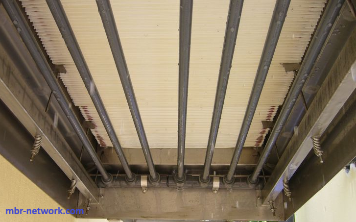
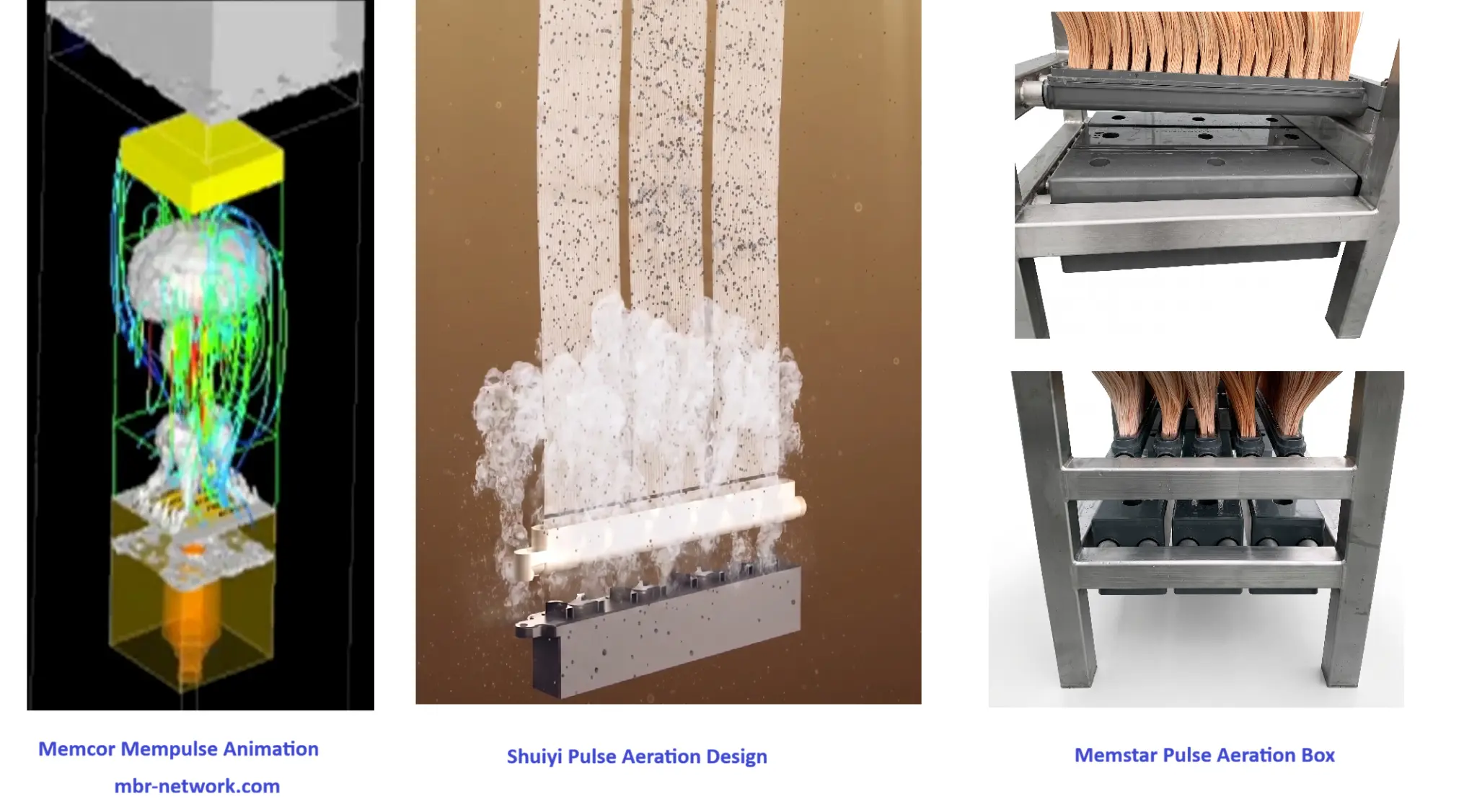
The first shows a submerged membrane assembly with parallel air-distribution pipes beneath the membrane elements. The second shows representative pulsed or large-bubble module arrangements.
Continuous coarse-bubble air scouring. The first photograph shows the underside of a submerged membrane assembly and its parallel air-scour distribution pipes. In this arrangement, air released below the module rises through the membrane zone, transferring momentum to the mixed liquor and helping maintain circulation and surface shear. The effectiveness of the arrangement depends on diffuser spacing, module footprint, water depth, air distribution, and the absence of blocked or preferential flow paths.
Intermittent or cyclic air scouring. Cyclic aeration alternates between higher-air and lower-air or no-air periods. It needs valves or equivalent switching hardware to control the air-flow pattern, so it adds control complexity while trying to save scouring energy. The approach can be useful when the membrane system has validated fouling-response data and reliable sequencing, but it requires suitable instrumentation, alarms, return-to-protective logic, and maintenance of the switching hardware.
Pulsed or slug air scouring. The second photograph shows representative pulsed or large-bubble module concepts. Pulsed aeration has become a mainstream design approach in many contemporary immersed MBR products. It can be more efficient through proprietary or patented module and air-distribution designs, and some designs do not need the same cyclic control valves because the pulse is generated by module geometry, airlift paths, air chambers, or other internal features. The exact arrangement remains supplier-specific; the selected OEM should document how the pulse is created, how it circulates mixed liquor through the module, and how membrane-fibre or plate movement remains within its approved limits.
Module-integrated airlift and cross-flow. In this arrangement, air is introduced at a location that intentionally induces mixed-liquor circulation through, between, or around the membrane elements. Air is therefore part of the module’s hydrodynamic architecture rather than only a source of bubbles below an external grid. The design should be assessed using module-level permeability, air demand, distribution, maintenance access, and cleaning-recovery evidence.
Hybrid fouling-control sequences. Air scouring may be coordinated with relaxation, permeate backwash or backpulse, mechanical mixing, chemically enhanced backwash, or other validated cleaning steps. The benefit comes from the complete sequence, not from assuming that one air pattern is sufficient under every loading condition. The sequence must be checked against membrane-material compatibility, permeate-quality requirements, chemical safety procedures, and the supplier’s operating envelope.
Air distribution, control, and design evolution. Blowers, headers, isolation devices, flow measurement, pressure measurement, and module-level distribution determine whether the intended air reaches the active membrane area. Modern designs increasingly integrate these elements with the module hydrodynamics and use permeability, TMP, flux, MLSS, viscosity, train status, and fouling indicators to avoid applying one fixed air rate to every condition. A technically credible comparison should therefore show the air path, the membrane area online, the operating flux, and the measured fouling response rather than relying on an equipment label alone.
These photographs are representative technical examples rather than universal module designs. Manufacturer-specific airlift, pulsing, diffuser, or control claims should be checked against the selected supplier’s documentation, reference plants, and site-specific commissioning data. If additional photographs or original schematics are added later, they should identify the module arrangement and air-flow direction clearly and should retain the appropriate source credit.
Practical decision summary
For a small plant with stable loading and limited controls expertise, a well-distributed continuous coarse-bubble system may offer the best balance of reliability and maintainability. For a larger plant with multiple trains, variable loading, measurable fouling trajectories, and capable instrumentation, intermittent, pulsed, module-integrated, or adaptive systems may justify their additional controls and commissioning effort.
The most defensible selection is the one supported by comparable module-level evidence: stable permeability, acceptable cleaning recovery, adequate fouling control, controllable air demand, maintainable equipment, and a whole-life cost that remains reasonable across minimum, average, peak, and future operating conditions. Air scouring should be optimized as part of the membrane module, biological process, blower, cleaning, and control-system package rather than purchased as an isolated diffuser item.
Related MBR Network pages
- MBR Membrane Technology Index
- Membrane Types & Materials
- Fouling Mechanisms, Monitoring & Prevention
- Membrane Cleaning: CEB, CIP, Soaking & Recovery
- Membrane Integrity & Module Management
- MBR Monitoring & Troubleshooting
- Membrane Flux, Area & Train Sizing Calculator
- Membrane Air-Scour Demand Calculator
- MBR Energy & Operating Cost Calculator
References
- The MBR Site, “Process and membrane aeration.” Specialist overview of membrane-scouring aeration, coarse-bubble aerators, SADm, SADp, and the distinction between membrane and process aeration.
- Jun, C., Aghasadeghi, K. & Daigger, G.T., “Optimizing Air Scouring Energy for Sustainable Membrane Bioreactor Operation by Characterizing the Combination of Factors Leading to Threshold Limiting Conditions,” Membranes, 2024, 14(3), 58. Peer-reviewed full-scale analysis of air-scouring energy, fouling-limiting conditions, and data-driven air-flow optimization.
- DuPont Water Solutions, “Membrane Bioreactor (MBR) — MemPulse™/MemCor™ system.” Manufacturer description of a module-integrated large-bubble, airlift, and cross-flow membrane-scouring approach; vendor claims should be validated for the selected system.
- U.S. Environmental Protection Agency, “Wastewater Management Fact Sheet: Membrane Bioreactors.” Public-sector overview of MBR applicability, advantages, disadvantages, energy, and operating considerations.
- The MBR Site, “Sidestream tubular MBR membranes: a summary of commercial products.” Specialist history and comparison of sidestream tubular MBRs, immersed configurations, module arrangements, and cross-flow implications.
- Rahman, T.U. et al., “The Advancement in Membrane Bioreactor (MBR) Technology toward Sustainable Industrial Wastewater Management,” Membranes, 2023, 13(2), 181. Peer-reviewed review covering MBR configuration history, structural features, operating parameters, and broad side-stream versus submerged trade-offs.
Revision note: This guide is intended as an educational technical reference. Review source dates, supplier data, and site-specific design assumptions before using it for procurement or plant operation. Future revisions should add validated user-supplied photographs and, where available, anonymized operating data showing air rate, flux, TMP, permeability, and energy response.