
Treatment Processes
Anaerobic Membrane Bioreactor (AnMBR): Design, Operation & Limits
Anaerobic membrane bioreactors combine anaerobic conversion with membrane solids retention. They can reduce aeration demand and produce biogas, but they are not a direct low-energy substitute for an aerobic MBR: low-strength wastewater, dissolved methane, membrane fouling, nutrient carryover, gas hazards, and temperature sensitivity can determine whether the process is suitable.
What an AnMBR changes
In an aerobic MBR, air supplies oxygen for biological oxidation and membrane scouring. In an AnMBR, microorganisms convert biodegradable organics through hydrolysis, acidogenesis, acetogenesis, and methanogenesis. The membrane retains suspended solids and slow-growing anaerobic biomass while allowing hydraulic retention time (HRT) and solids retention time (SRT) to be selected more independently. The result can be a low-solids permeate, lower biological sludge production, and biogas recovery. The same separation does not remove dissolved nutrients, dissolved methane, or every soluble contaminant.
The technology is most defensible where the wastewater has sufficient biodegradable organic strength, the temperature and alkalinity support methanogenesis, gas handling is engineered from the beginning, and the final treatment objective is defined. Mainstream municipal sewage remains more difficult than many high-strength industrial applications because its COD concentration and methane energy per cubic metre are low while pumping, pretreatment, membrane control, and possible heating loads remain.
When is AnMBR a reasonable candidate?
| Screening question | Evidence to collect | Interpretation |
|---|---|---|
| Is the organic load sufficient? | Flow-proportional COD fractions, biodegradability, temperature, sulfate, salinity, toxicity, and daily variability. | Low-strength wastewater may not generate enough recoverable methane to offset membrane and ancillary energy. |
| Can methanogens remain stable? | pH, alkalinity, VFA profile, ammonia, sulfide, temperature, methane rate, and load history. | Rising VFA with falling alkalinity or methane rate is an instability signal, not a condition to correct from a generic dose. |
| Can the membrane be operated economically? | Configuration, flux, MLSS/solids inventory, gas-scour or crossflow demand, relaxation, cleaning, replacement, and access. | Compare lifecycle cost and energy. A high flux can reduce area but accelerate fouling and cleaning. |
| What happens to permeate? | Reuse or discharge limits for COD, ammonia, total nitrogen, phosphorus, sulfide, pathogens, dissolved methane, micropollutants, and salinity. | Membrane solids separation is not a complete post-treatment train. |
| Can gas hazards be controlled? | Gas-space layout, ventilation, methane/LEL and H2S detection, pressure protection, flare or utilisation, electrical classification, and confined-space procedures. | Do not progress from biological feasibility to construction without an engineered gas-safety basis. |
Two common AnMBR process arrangements
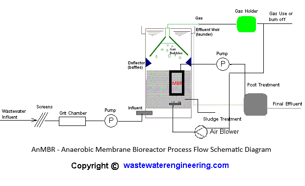
The immersed arrangement below is reproduced from the Wastewater Engineering Group AnMBR process-flow page for orientation. Follow the original page for its source context. The diagram is a conceptual representation, not a project design drawing.
A sidestream arrangement places the membrane outside the anaerobic reactor. A recirculation pump drives mixed liquor through the membrane module, returns retentate to the reactor, and sends permeate to the downstream treatment train. The external loop can simplify access and inspection, but its pump energy, pressure, heat generation, shear, gas separation, and isolation requirements must be included in the mass and energy balance.
Diagram boundary. The Mermaid flow is a simplified sidestream concept. Actual membrane staging, recycle routing, gas separation, cleaning connections, instrumentation, standby capacity, and safety devices depend on the selected OEM and project design.
Immersed versus sidestream suitability
| Arrangement | More suitable when | Main trade-offs to verify |
|---|---|---|
| Immersed AnMBR | Lower filtration energy, compact installation, and direct membrane immersion are priorities; the project can provide effective biogas scouring, reliable pretreatment, controlled flux, and a safe method for module isolation and removal. | Gas-scouring energy, submerged access, physical cleaning, membrane lifting, reactor-space requirements, gas distribution, and the effect of solids and temperature on fouling. |
| Sidestream AnMBR | High-strength or variable wastewater benefits from accessible external modules, controlled crossflow, easier inspection, and a more direct membrane-cleaning or replacement arrangement. | Recirculation power, pressure, heat, shear, pump reliability, retentate routing, gas-liquid separation, standby equipment, and the full lifecycle cost of the external loop. |
Biological stability: monitor the cause before the symptom
AnMBR biology is a chain of dependent reactions. Hydrolysis and acidogenesis can continue while methanogenesis is inhibited, so pH may remain near neutral for a period even as VFAs accumulate. A useful control picture therefore combines the following trends rather than relying on one number:
- VFA and alkalinity: use the site-approved analytical method and trend their relationship. Increasing VFA with declining buffer capacity indicates that acid production is exceeding methanogenic conversion or that an inhibitor is present.
- Methane rate and composition: measure gas flow, methane fraction, carbon dioxide, H2S, pressure, temperature, and condensate. A gas-flow reduction can reflect biology, leakage, dissolved methane, measurement error, or a change in feed composition.
- pH and temperature: methanogens generally favour near-neutral pH. Mesophilic operation is commonly around 30–38 °C, while ambient operation around 15–25 °C has been demonstrated but with slower kinetics and greater SRT and fouling pressure. Published ranges are context, not universal setpoints.
- Organic loading and hydraulics: calculate HRT, SRT, organic loading rate, recycle, and wasting from actual flow and mass data. Membrane retention can allow a long SRT, but it cannot remove the risk of acidification from a sudden load or toxic shock.
- Inhibitors: review sulfate, sulfide, free ammonia, salinity, solvents, disinfectants, metals, and cleaning carryover. The effect depends on pH, temperature, acclimation, and exposure duration.
Literature reviews commonly report municipal AnMBR HRT values of roughly 6–24 hours, long SRT values from several tens to hundreds of days, and study-specific organic loading rates in the approximate range of 0.3–2.9 kg COD/m3/d. These figures should be used to frame a pilot envelope, not copied into a final design. [1]
Membrane configuration and fouling-control choices
Submerged membranes usually operate at lower filtration pressure and use biogas sparging, relaxation, permeate backwash, or a combination of controls. They can reduce filtration energy, but membrane access and physical cleaning are more difficult. Gas-scour intensity should be optimised to the minimum effective level because sparging can become a dominant energy demand.
Sidestream or external membranes use tangential circulation across the membrane surface. The shear can help manage deposition and modules may be easier to isolate, inspect, and clean. The disadvantages are recirculation energy, pressure, heat generation, shear exposure, and additional equipment.
Fouling control should be designed as a layered system:
- Protect the membrane: provide screening, grit control, equalisation, and source control appropriate to the feed. Pretreatment reduces debris and particulate loading but does not eliminate soluble microbial-product or inorganic fouling.
- Operate below the site-specific critical flux: use flux, TMP, permeability, solids concentration, and normalised trends together. A higher flux can reduce membrane area and increase capital efficiency while raising fouling and cleaning risk.
- Use hydrodynamics deliberately: optimise gas distribution, crossflow, relaxation, and backwash duty rather than maximising gas or pump flow. Pilot testing should establish the minimum effective control envelope.
- Separate reversible and irreversible fouling: relaxation and physical controls address reversible cake. Chemical cleaning is for foulants that remain after the approved physical sequence, and must follow membrane, biology, chemical, and discharge compatibility requirements.
Lower temperature can slow digestion, increase viscosity, change microbial products, and worsen fouling. A municipal pilot reported lower methane yield and more dissolved methane at 15 °C than at 25 °C while COD removal remained high, illustrating why membrane effluent quality alone can hide a deteriorating energy balance. [2]
Methane recovery: count gas-phase and dissolved methane separately
The methane measured at a gas meter is not necessarily the methane produced. A portion can remain dissolved in the permeate, particularly at lower temperature and under pressure. Dissolved methane reduces recoverable energy and can become a greenhouse-gas emission if it is released downstream without capture or oxidation.
A project mass balance should distinguish at least:
- COD fed, COD removed, COD converted to biomass, COD reduced to sulfate, and COD converted to methane;
- methane recovered in the gas phase, methane dissolved in permeate, methane lost in off-gas or leaks, and methane consumed or oxidised downstream; and
- gross methane energy, parasitic pumping and scouring energy, heating energy, gas conditioning, methane-recovery equipment, membrane cleaning, and replacement.
Degassing membrane contactors and other recovery systems may be appropriate in some designs, but they introduce additional equipment, wetting, vacuum or sweep-gas control, off-gas management, and maintenance questions. Select the recovery method only after measuring dissolved methane under representative pressure, temperature, flux, and load conditions. [3]
Gas safety is a process requirement, not an accessory
Before commissioning, verify gas-tightness and pressure/vacuum protection. Calibrate and bump-test methane/LEL, H2S, O2, and any required CO2 instruments. Prove alarm actions, ventilation interlocks, emergency shutdowns, isolation valves, relief paths, flare ignition or utilisation permissives, condensate drainage, backup power, and safe restart logic. The exact alarm and shutdown values must be taken from the approved safety basis, not from this article.
Permeate and downstream treatment
An AnMBR can provide strong suspended-solids and particulate-COD separation, but soluble nutrients commonly pass through. Ammonium and phosphate may remain in the permeate, and additional barriers may be needed for sulfide, residual VFAs, pathogens, colour, salinity, micropollutants, and dissolved methane. Possible downstream families include nitrification-denitrification, anammox, chemical phosphorus precipitation, adsorption or ion exchange, polishing membranes, degassing, nutrient recovery, and disinfection. The correct train depends on the permit or reuse specification and the measured permeate composition.
Define downstream treatment before selecting the reactor. Otherwise the AnMBR may be optimised for methane production while the overall plant still fails its nitrogen, phosphorus, pathogen, greenhouse-gas, or reuse objective. [4]
Commissioning and operating verification
| Stage | Verify | Hold point |
|---|---|---|
| Before feed | Membrane integrity, valve position, leak and pressure tests, instrument calibration, gas detector bump tests, ventilation, relief, flare/utilisation, E-stop, isolation, and sampling plans. | Do not introduce anaerobic gas until containment, detection, ventilation, and emergency actions are accepted. |
| Biological start-up | Seed condition, temperature, pH, alkalinity, VFA, ammonia, sulfide, gas flow/composition, permeate quality, solids inventory, and feed loading. | Increase loading only when the approved stability indicators and methane response support the next step. |
| Filtration start-up | Flux, TMP, permeability, gas-scour or crossflow, relaxation, backwash, MLSS, particle size, and fouling rate. | Use OEM limits and pilot-derived control ranges; do not compensate for an unstable biology by forcing membrane flux. |
| Normal operation | Trend mass balance, gas losses, dissolved methane, energy, cleaning frequency, chemical use, membrane integrity, and downstream compliance. | Review the whole plant when methane recovery, permeability, VFA, nutrient, or safety trends move together. |
| Upset and restart | Cause isolation, toxic-load review, controlled feed reduction, gas-space safety, membrane condition, sampling frequency, and restart criteria. | Restart from the approved recovery procedure. Do not use generic alkalinity, chemical, flux, or SRT changes. |
Related design resources and boundaries
References and revision note
This guide is an educational engineering reference. It does not replace an approved process design, pilot programme, permit, gas-safety plan, hazardous-area assessment, confined-space procedure, control-system standard, laboratory method, or membrane manufacturer instruction. Reported values are literature context and may not transfer between wastewater types, temperatures, membrane configurations, or operating strategies. Last reviewed: September 26, 2026.
- Kanafin et al., “Anaerobic Membrane Bioreactors for Municipal Wastewater Treatment: A Literature Review.”
- Ji et al., “Temperature impacts, dissolved methane, and fouling in a municipal AnMBR pilot.”
- Velasco et al., “Recovery of Dissolved Methane From AnMBR Using Degassing Membrane Contactors.”
- Zielińska et al., “Anaerobic Membrane Bioreactors (AnMBRs) for Wastewater Treatment.”
- U.S. EPA AgSTAR, “How Does Anaerobic Digestion Work?”
- CDC/NIOSH Pocket Guide, “Hydrogen Sulfide.”
- Wastewater Engineering Group, “AnMBR - Anaerobic Membrane BioReactors for Wastewater Treatment.” Original immersed process-flow diagram source.